English
 中文简体
中文简体 Deutsch





Content
- 1 What Is a Lap Joint Stub End and Why Does It Exist?
- 2 Critical Dimensions You Must Verify Before Specifying a Stub End
- 3 How to Install a Lap Joint Stub End Assembly Properly
- 4 Material Selection: Pipe Compatibility and Corrosion Control
- 5 Where a Lap Joint Stub End Is Not the Right Choice
- 6 Frequently Asked Questions About Lap Joint Stub Ends
At a food processing plant, a 6-inch ASME Class 150 lap joint stub end with a long pattern measures 152.4 mm in length and 219.1 mm across the lap face. Installers value these numbers because the backing flange rotates independently, eliminating field rework when bolt holes refuse to line up.
At its core, a lap joint stub end is a flared pipe sleeve welded to the pipe and pressed against a loose flange. The flange never touches the pipe; it backs the stub end and transfers gasket load. This makes bolt-hole alignment, gasket replacement, and pipe inspection far easier than with a fully welded flange.
What Is a Lap Joint Stub End and Why Does It Exist?
A lap joint stub end is a two-piece flange connection where a flared pipe sleeve is welded to the pipe and a loose backing flange applies the gasket load.
A stub end is a pipe fitting with a flared end that mates with a lap joint flange. The fitting is welded to the pipe, while the flange remains loose and freely rotating around the pipe axis.
The stub end's flared lap face matches the gasket face of the backing flange. Because the flange is not welded to the pipe, it can rotate 360 degrees around the pipe axis before bolts are tightened. That freedom is the defining advantage over slip-on or weld-neck flanges.
360
Degrees of flange rotation freedom
2
Components per connection
0
Welds on the flange itself
The design also shortens maintenance time. Once the bolts are loosened, the flange can be pulled back past the gasket, allowing the gasket to be replaced without cutting the pipe. In food and pharmaceutical plants, where hygienic lines are inspected frequently, this reduces downtime considerably.
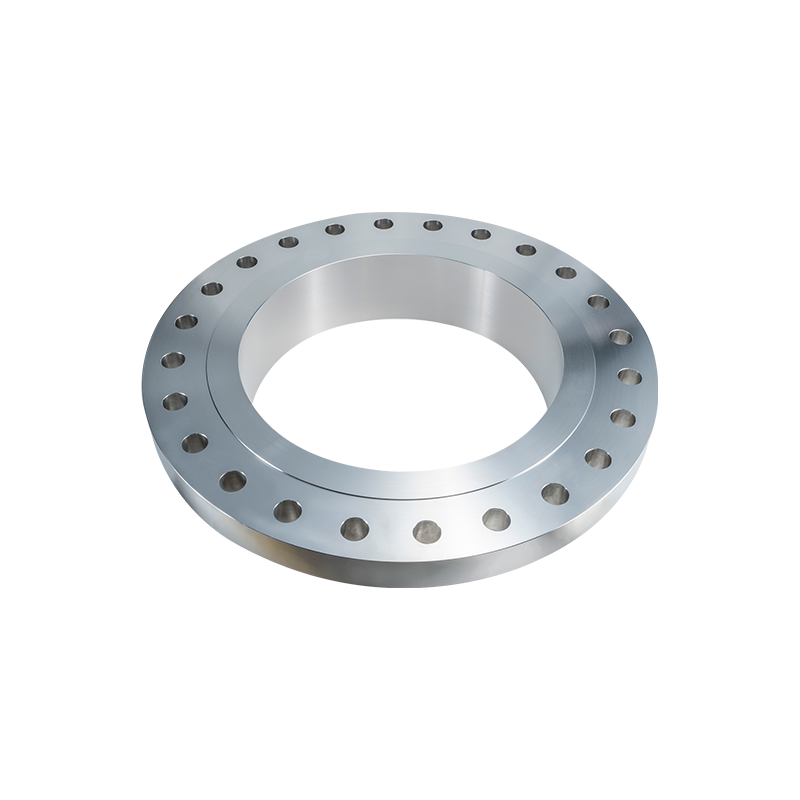 Stainless Steel Lap Joint Flange for Quick-Disconnect Piping SystemsThis lap joint flange works with a stub end to allow fast disassembly and gasket replacement without cutting the pipe, reducing downtime in hygienic lines. It offers flexible bolt alignment and is available with alloy stub ends for cost-effective corrosion resistance.View Product →
Critical Dimensions You Must Verify Before Specifying a Stub End
Stub end dimensions follow ASME B16.9 for the fitting and ASME B16.5 for the flange face. The three numbers that matter most are stub end length, lap diameter, and lap thickness.
Stub end length determines how the fitting seats in the pipe run and whether the gasket is fully supported. ASME B16.9 defines short and long patterns. Short pattern stub ends are used when space is tight, but they require a thicker gasket and careful bolt spacing. Long pattern stub ends provide a larger bearing surface and better gasket stability.
Lap Diameter by Nominal Pipe Size (ASME B16.9 Long Pattern)
1 inch NPS - 50.8 mm
2 inch NPS - 88.9 mm
3 inch NPS - 127.0 mm
4 inch NPS - 152.4 mm
6 inch NPS - 219.1 mm
The chart shows how the lap diameter grows with pipe size. For a 6-inch line, the lap face spans 219.1 mm, while a 1-inch stub end has just a 50.8 mm lap face. Match the lap diameter with the flange bore specification before ordering.
| NPS | Pipe OD (mm) | Stub End Length (mm) | Lap Diameter (mm) |
| 1 | 33.4 | 76.2 | 50.8 |
| 2 | 60.3 | 76.2 | 88.9 |
| 3 | 88.9 | 76.2 | 127.0 |
| 4 | 114.3 | 152.4 | 152.4 |
| 6 | 168.3 | 152.4 | 219.1 |
The lap thickness should also be checked against the flange pressure rating, especially for Class 900 and Class 1500 services where the gasket seating loads are much higher.
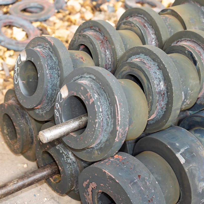 Class 900 Lap Joint Flange for High-Pressure ServiceDesigned for high-pressure systems, this Class 900 flange pairs with a stub end to provide a rotating ring that eases alignment and maintenance. It suits applications needing frequent cleaning or corrosion-resistant materials, with pressure testing to ensure stability.View Product →
How to Install a Lap Joint Stub End Assembly Properly
Install a lap joint stub end assembly by sliding the backing flange onto the pipe before welding the stub end. Welding the stub end first traps the flange behind the weld bead and makes the connection unusable.
- Cut the pipe square and deburr both the inner and outer diameter.
- Slide the lap joint flange onto the pipe with the flange face oriented away from the weld.
- Push the stub end over the pipe until its lap face sits flush against the flange.
- Weld the stub end to the pipe using a full-penetration joint per the piping specification.
- Place the gasket between the stub end lap face and the mating flange face.
- Align bolt holes, insert bolts, and tighten in alternating sequence to the specified torque.
The most common field error is welding the stub end to the pipe after the flange has already been installed. Once the weld is complete, the flange cannot rotate past the weld bead. Always slide the flange on first.
After welding, inspect the lap face for splatter, nicks, or scratches. A damaged lap face can cause a gasket to leak even at moderate pressure. Use a straightedge to verify the lap face is flat and parallel to the flange face.
Material Selection: Pipe Compatibility and Corrosion Control
Match the stub end material to the pipe and process fluid first; the backing flange can be a lower-cost carbon steel even when the stub end is high alloy.
Cost-Optimized Approach
A105 carbon steel stub end with a carbon steel lap joint flange. This option handles steam, cooling water, hot oil, and other non-corrosive services.
Full Alloy Approach
F316/316L stainless steel stub end with a matching F316 lap joint flange. This approach is preferred for food, pharmaceutical, and aggressive chemical service.
| Material | Temperature Range | Typical Application |
| A105 Carbon Steel | -29 C to 425 C | Steam, utility water, hot oil |
| F304/304L | -196 C to 650 C | Nitric acid, food processing |
| F316/316L | -196 C to 600 C | Chlorinated water, chemical plants |
| Duplex S31803 | -50 C to 300 C | Seawater, offshore, pulp mills |
The stainless steel grades used for stub ends follow the same selection logic outlined in the stainless steel flange selection guide. When the fluid contains chloride or pitting agents, upgrade to duplex, super duplex, or nickel-based alloys.
The trade-off between the cost-optimized and full-alloy approaches is not just material expense. A carbon steel flange with a stainless stub end gives corrosion resistance where it matters at the gasket face, while keeping the flange cost low. That advantage matters in large-diameter, high-pressure piping systems.
As a manufacturer with ISO 9001 and PED certifications, Jiangyin Zhonghai Precision Machinery Co., Ltd. produces lap joint stub ends and backing flanges in carbon steel, stainless steel, duplex, and nickel-based alloys, including non-standard dimensions machined to customer drawings.
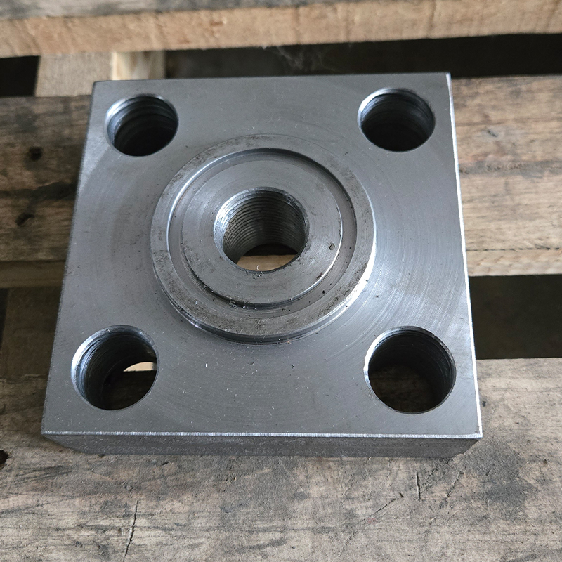 F316/316L/316Ti Stainless Steel Flange for Corrosive EnvironmentsThis forged stainless steel flange offers excellent resistance to corrosion and intergranular attack, making it suitable for petrochemical and marine services. Manufactured under strict controls, it meets ASME standards and is available in custom sizes up to 4 meters.View Product →
Where a Lap Joint Stub End Is Not the Right Choice
A lap joint stub end is the wrong choice for vacuum service, high-cycle fatigue, and high-temperature lines with significant pressure spikes.
- Vacuum service. The loose flange relies on gasket compression. At negative pressure, atmospheric pressure can lift the flange and create a leak path.
- High-vibration or cyclic piping. Fatigue loads concentrate at the stub end's lap face because the flange is not welded, so micro-cracks can propagate over time.
- Creep relaxation at elevated temperatures. The gasket load can fade as the stub end and flange metal relaxes, leading to gradual leakage.
- Hygienic lines that require internal drainability. The gap between the stub end and the flange can trap solids or bacteria.
For these services, a weld-neck flange or a slip-on flange with full fillet welds provides a more rigid, leak-resistant connection. If a lap joint is unavoidable in a marginal service, specify a raised-face flange with a spiral wound gasket and monitor the connection periodically.
Frequently Asked Questions About Lap Joint Stub Ends
Is a lap joint stub end suitable for high-pressure lines?
Yes. The lap joint stub end design appears in ANSI Class 900 and higher pressure classes. Verify the stub end wall thickness, lap thickness, and gasket seating load against operating conditions. The flange pressure rating governs the maximum allowable pressure.
How do I select the right stub end length for my pipe?
Select a long-pattern stub end when the pipe size is 4 inches and above to ensure enough space for the gasket and flange. Short-pattern stub ends are used for space-constrained runs, but they require thicker gaskets and careful bolt spacing.
What gasket type works best with a lap joint stub end assembly?
Spiral wound gaskets with a stainless steel outer ring work best for high-pressure and high-temperature service. For moderate conditions, a non-asbestos sheet gasket such as aramid fiber or PTFE provides adequate sealing, provided the lap face is smooth and free from scratches.
Can a stub end be rotated after welding during field assembly?
No. Once welded, the stub end cannot be rotated or repositioned without cutting the weld. Field adjustments are limited to the flange orientation before tightening the bolts. If a mistake is made, the weld must be ground out and redone.
 Previous