English
 中文简体
 Deutsch






Content
- 1 What a Bleeder Blind Is and Where the Port Belongs
- 2 Where Bleeder Blinds Earn Their Place
- 3 Bleeder Blind, Standard Blind Flange or Bleeder Ring
- 4 Selecting Pressure Class, Port Size and Plate Thickness
- 5 Material Choice Follows the Medium, Not the Port
- 6 Machining, Testing and Documentation
- 7 What to Put on the Datasheet
- 8 Practical Questions Buyers and Engineers Ask
A 24-inch Class 150 blind flange is bolted to the end of a suction header. The line fills for a hydrostatic test, the pump runs, the gauge climbs to 19.6 bar (285 psi), and the header is still only 85 percent full of water. The gauge is reading an air pocket, not the water. A bleeder blind exists because that pocket has to go somewhere before the test sheet can be signed.
The part itself is simple: a blind flange with one small port through the plate. What decides whether it works is where the port sits, how it is threaded, how much plate is left around it, and whether the material still matches the line it is closing. Those four questions drive every specification decision below.
What a Bleeder Blind Is and Where the Port Belongs
A bleeder blind is a blind flange with a single small port machined through the plate so air, water or test medium can be released without breaking the bolted joint.
Working definition
A bleeder blind, also called a bleeder flange or vent blind, is a blind flange in which one opening, normally NPS 1/2 to NPS 1, is drilled and either tapped to ASME B1.20.1 NPT or fitted with an ASME B16.11 half-coupling, then closed with a plug, nipple, gauge or small valve.
Port placement is the first thing a designer gets wrong. The hole belongs inside the gasket pitch circle, at the center of a raised face, so the annular band where the gasket actually seats stays unbroken. A port drilled outside that circle, or through the raised face edge, leaves a leak path that no torque value will fix. On flat-face blinds the same rule applies: inside the bolt circle, inside the gasket contact ring, nowhere near the bolt holes.
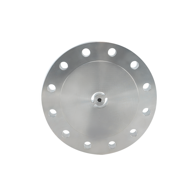 Forged Blind Flange for Sealed Pipe EndsForged blind flange in sizes 1/2 to 60 in with RF, FF, and RTJ faces; port placement and three build styles support leak-free sealing.View Product →
Three build styles cover most orders. The tapped-plate version threads directly into the blind and suits plate thick enough to carry full thread engagement. The welded-boss version adds a half-coupling on the outside face, which keeps the sealing face clean and lets thin blinds accept a port. The third style carries a jack-screw arrangement, used where a blind has to be cracked open against residual pressure during maintenance.
Where Bleeder Blinds Earn Their Place
Bleeder blinds are installed at the two points of a line that matter most: the high point where air collects during filling, and the low point where water sits after the test is drained.
Hydrostatic testing is the largest single use. ASME B31.3 Para. 345.4 sets the strength test at 1.5 times design pressure with a hold of at least 10 minutes, and a line holding an air pocket will not reach stable pressure in that window. Venting through a bleeder port removes the compressible volume and makes the gauge tell the truth. Drain duty follows close behind: a sump dimple at the lowest point of the blind lets the test water leave instead of sitting against the gasket for weeks.
| Duty | Port position | Typical port size | Governing reference |
| High-point air vent during hydrotest | Center of raised face | NPS 1/2 | ASME B31.3 Para. 345 |
| Low-point drain after test | Lowest point, with sump dimple | NPS 3/4 | ASME B16.5 |
| Pump suction priming | Center, plug or gate valve | NPS 1/2 to 3/4 | ASME B16.5 Class 150 |
| Water main air release | Near the crown of the pipe | NPS 1/2 | AWWA C207 |
| Sample or injection point | Off-center, dip tube optional | NPS 1/2 | Project specification |
Water and wastewater work uses the part so often that AWWA C207 blind flanges are frequently ordered pre-tapped. Pump suction lines, tank nozzles and test headers on packaged skids repeat the same pattern: one blind, one port, one plug.
Bleeder Blind, Standard Blind Flange or Bleeder Ring
A standard blind flange seals a line, a bleeder blind seals and vents it, and a bleeder ring vents without removing the blind at all.
Standard blind flange
Full plate, no opening. Highest integrity, lowest cost, and the correct choice where venting happens through a separate valve or a line high point. It cannot release trapped air without unbolting.
Bleeder blind
One port through the plate, plugged in service. Adds vent, drain and gauge access at the exact point needed. Requires a reinforcement check and a thread that matches the plug supply chain.
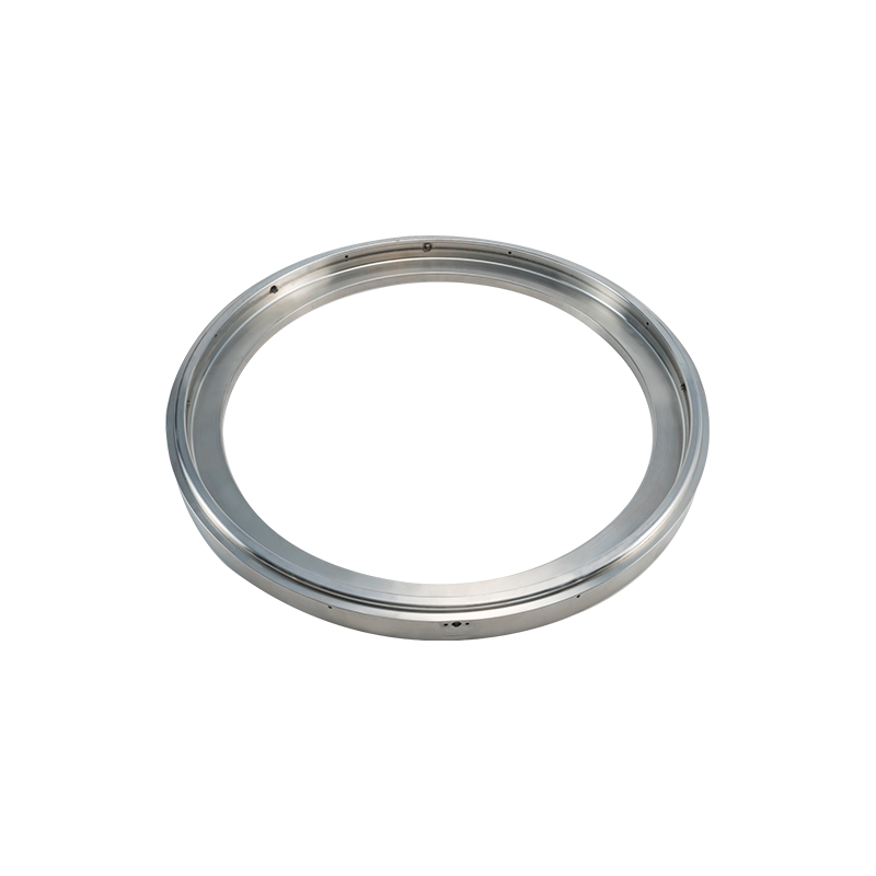
The bleeder ring, sometimes called a drip ring, is a thin annular spacer that fits between two flange faces and carries its own small port. It is chosen when the blind must stay untouched, or when a line needs a permanent drain point without machining the blind. The trade-off is a second gasket joint, and every added joint is an added leak path on a pressure test.
Selecting Pressure Class, Port Size and Plate Thickness
Pressure class follows the line, not the port: a bleeder blind carries the same ASME B16.5 rating as the flange it replaces, and the port must be sized so it does not undercut that rating.
| Class | Rating at 38 °C | Equivalent psi | Common port |
| 150 | 19.6 bar | 285 | NPS 1/2 |
| 300 | 51.1 bar | 740 | NPS 1/2 to 3/4 |
| 600 | 102.1 bar | 1480 | NPS 3/4 |
| 900 | 153.2 bar | 2220 | NPS 3/4 to 1 |
| 1500 | 255.9 bar | 3705 | NPS 1 |
| 2500 | 425.5 bar | 6170 | NPS 1, welded boss |
Port size scales with line volume, because fill and drain time do. The chart below reflects the practice that holds up on site without creating an oversized opening in a small plate.
Recommended bleeder port by line size
NPS 2
1/2 in
NPS 6
1/2 in
NPS 12
3/4 in
NPS 24
1 in
NPS 36
1-1/2 in
Reinforcement is the technical question buyers ask last and should ask first. ASME B31.3 Para. 304.3.3 treats an opening in a pressure part as a branch connection and calls for a reinforcement calculation unless the opening is small enough to be exempt. A tapped hole that carries full thread engagement through the plate thickness is widely accepted without a pad, but the calculation remains the designer's responsibility, and it changes quickly once the port moves above NPS 1. An up-to-date blind flange size chart is the fastest way to confirm the plate thickness you are working with before a port is assigned.
Material Choice Follows the Medium, Not the Port
The bleeder port does not change the material selection rule: the blind must match the pipe, the gasket and the operating temperature of the line it closes.
| Material | Specification | Service window |
| Carbon steel | ASTM A105 | Water, air, oil, steam to about 425 °C |
| Low-temperature carbon steel | ASTM A350 LF2 | Down to -46 °C impact-tested service |
| Austenitic stainless | ASTM A182 F316L | Dilute acids, seawater, hygienic lines |
| Duplex stainless | ASTM A182 F55 | Chloride stress cracking, offshore topsides |
| Chrome-moly alloy | ASTM A182 F22 | High-temperature steam and hydrogen service |
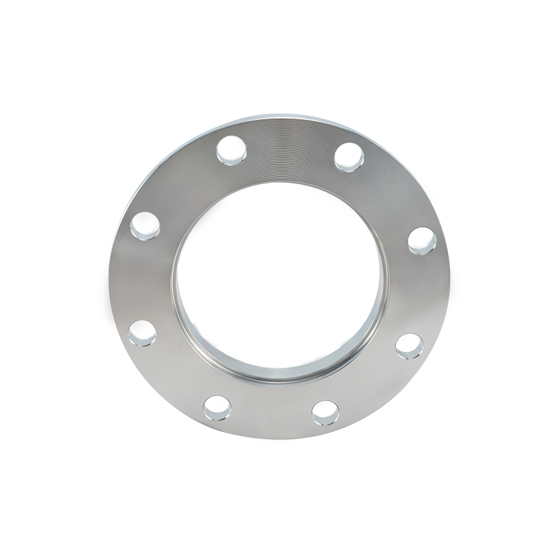 Custom A105 Carbon Steel FlangeASTM A105 forged flange in sizes 1/2 to 60 in and Class 150–2500, suited to bleeder ports when plug material is compatible.View Product →
Two material details matter more on a bleeder blind than on a plain blind. First, the plug or valve screwed into the port must be at least as corrosion resistant as the blind, or the assembly fails at the thread rather than the plate. Second, a stainless plug in a carbon steel port creates a galvanic couple in wet service; a compatible material pair or an isolating sealant prevents the thread from seizing within a season.
Machining, Testing and Documentation
A bleeder blind is only as good as its facing and its thread, so both are controlled at the machine and verified before shipment.
1.5x
Hydrostatic test pressure against design pressure, ASME B31.3 Para. 345.4
10 min
Minimum hold at test pressure before inspection
3.2-6.3 µm
Ra surface finish range for a raised face per ASME B16.5
Facing flatness is checked on a surface plate, not by eye. A raised face that deviates across the gasket band will leak at pressure regardless of bolt torque. Threads are gauged to ASME B1.20.1 with plug and ring gauges, and every port is checked for full engagement depth after tapping. Positive material identification is run on alloy heats so an F316L blind never leaves the floor with an F304 marking.
Marking follows ASME B16.5 Para. 4: size, class, material specification, heat number and manufacturer. Once a port is added, the drawing revision and the port specification belong on the paperwork as well, because the certified part no longer matches the catalog description. Full inspection routes and certificate packages are described in the plant's quality control process.
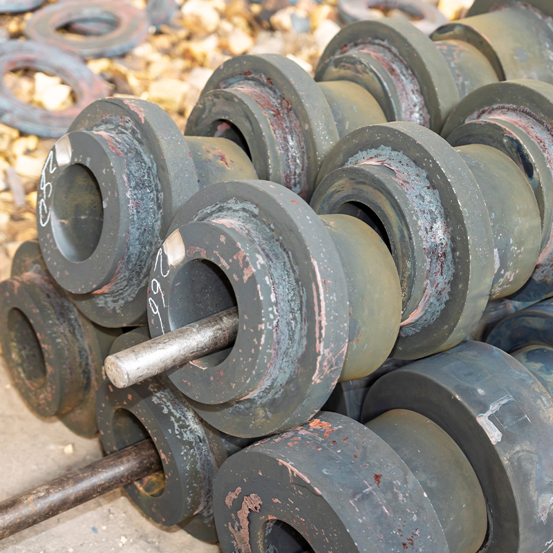 Non-Standard Forged Flanges Made to DrawingCustom forged flanges up to 60 in and 10 tons per piece, produced to drawings for non-standard bleeder blinds and specialty pressure connections.View Product →
Non-standard bleeder blinds, including offset ports, twin ports for simultaneous vent and drain, and oversized bosses for NPS 2 connections, are made to drawing rather than to a catalog table. Forging capacity runs to 60 inches and 10 tons per piece, which covers most test header and water main requirements without a welded fabrication.
What to Put on the Datasheet
Six lines on a purchase requisition prevent almost every bleeder blind mismatch we see returned.
- Flange size, pressure class and facing type, for example NPS 12, Class 150, raised face.
- Governing standard, such as ASME B16.5, EN 1092-1 Type 05 or JIS B2220 10K.
- Material specification with the heat treatment condition, for example ASTM A105 normalized.
- Port size, thread form and position, written as NPS 3/4 NPT at center of raised face.
- Plug or valve requirement, including material and whether it ships installed.
- Test and documentation requirements, including hydrotest pressure, PMI and the certificate type.
Add the fill volume and the medium to the notes if the port is expected to vent a large line quickly. A 3/4-inch port on a 500-meter header will pass air, but it will not pass it fast enough to shorten a commissioning window by a shift.
Practical Questions Buyers and Engineers Ask
Does a bleeder hole reduce the pressure rating of the blind?
Not if the opening stays within ASME B31.3 Para. 304.3.3. A single NPS 1/2 tapped port in a Class 150 blind of NPS 6 or larger leaves a ligament that satisfies reinforcement without a pad, while the same port in a smaller blind removes a larger share of the plate and should be calculated or moved to a welded boss.
Can a maintenance team drill and tap a blind in the field?
Only where the plate is thick enough for full thread engagement. A Class 150 NPS 2 blind is 12.7 mm thick per ASME B16.5, which is below the roughly 15 mm an NPS 1/2 taper thread needs, so the field modification either strips or leaks. It also breaks traceability: the heat number and material certificate no longer describe the part.
Which thread form should the port use?
ASME B1.20.1 NPT for ASME B16.5 projects, ISO 7-1 Rc or Rp for EN 1092-1 projects, and JIS B0203 where Japanese standards govern. Mixing forms across a project produces plugs that engage two turns and seal nowhere.
What port size does a 12-inch line need?
NPS 3/4 covers NPS 8 through NPS 14 lines in normal vent and drain duty. NPS 1/2 is adequate up to NPS 6, NPS 1 suits NPS 16 to NPS 24, and NPS 1-1/2 or larger is specified above NPS 30 where drain time is measured in hours.
A bleeder blind is a small, cheap part carrying a disproportionate share of the commissioning schedule. Get the port position, thread form and plate thickness right at the drawing stage, and the part disappears into the line where it belongs.
 Previous