English
 中文简体
 Deutsch






Content
- 1 What an Orifice Flange Is and What It Adds to a Weld Neck Flange
- 2 Class, Tap Size and Pressure Rating: The Numbers That Fix the Order
- 3 Material Selection: Match the Fluid First, the Temperature Ceiling Second
- 4 Five Tolerances That Decide Whether the Meter Reads Correctly
- 5 Jack Screws, Gaskets and the Installation Habits That Break Orifice Flanges
- 6 Sourcing Orifice Flanges: Standard B16.36 Pair or Custom Machining
- 7 Frequently Asked Questions About Orifice Flanges
A 12 in. Class 300 orifice flange pair can pass a full dimensional inspection and still bias a natural gas flow meter by more than 1 percent, because the pressure taps sit a few millimetres off the specified centerline and nobody measures them. An orifice flange is a metering component with a bolting pattern, not a bolting component with a hole drilled in it, and the purchase order has to say so.
That distinction decides what goes on the drawing. Outside diameter, bolt circle, thickness and facing are the dimensions a receiving inspector checks by habit, and every one of them can be correct on a flange pair that will never meter accurately. Tap position, tap orientation, tap bore condition and face finish are the dimensions that carry the measurement, and they are the ones that get skipped.
Orifice flanges are also the one flange family where a small machining error is hardest to catch downstream. A bad weld neck flange leaks and gets replaced within days. A bad orifice flange reads a stable, believable, slightly wrong number for years, and the error only surfaces during a meter audit or a custody transfer review.
What an Orifice Flange Is and What It Adds to a Weld Neck Flange
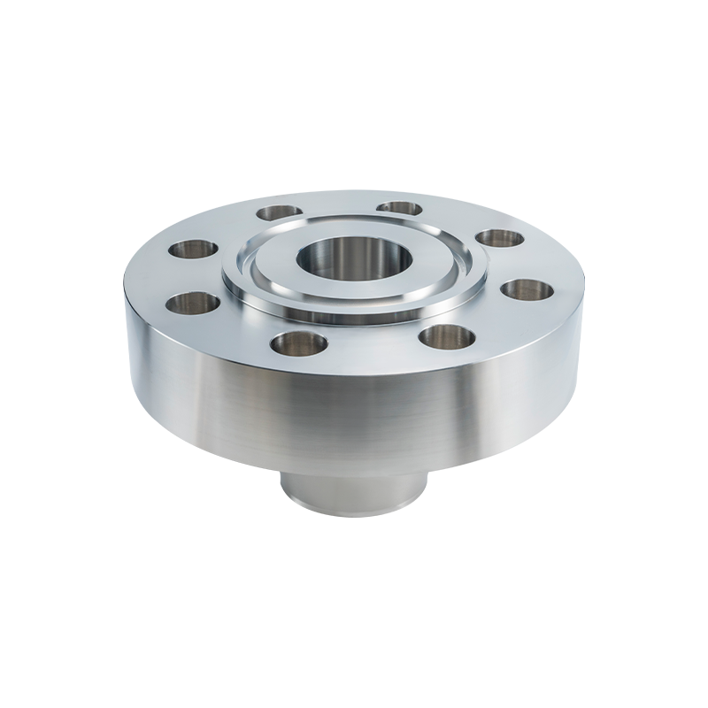
An orifice flange is a matched pair of pipe flanges, each carrying a radial pressure tap machined to a controlled distance from the flange face and a set of jack screws, that clamps an orifice plate between two pipe runs. The two taps feed the high and low legs of a differential pressure transmitter, and the transmitter converts the pressure difference into flow rate.
Core definition: an orifice flange is a flange pair that holds an orifice plate and carries two pressure taps plus jack screws for plate removal. The body dimensions follow ASME B16.5 or EN 1092-1; the tap and jack screw geometry follows ASME B16.36 or a project specification.
Take away the taps and the jack screws and you are holding a weld neck or slip-on flange. ASME B16.36 adds the orifice-specific geometry for NPS 1/2 through NPS 24 in Classes 300, 600, 900, 1500 and 2500, and it does so on top of standard B16.5 body dimensions. The flange still bolts to the same studs, the same gasket diameter and the same pipe size as the standard part it replaces, which is why orifice flanges are usually procured as drop-in replacements for a meter run rather than as a bespoke design.
They are quoted and supplied as a pair, because the two flanges must be drilled so that the taps line up in a single usable plane once the plate and both gaskets are installed. Ordering a single flange against an existing partner is possible, but the tap position then has to be referenced to the installed plate rather than to the flange face.
Class, Tap Size and Pressure Rating: The Numbers That Fix the Order
Class is the single largest cost and lead time driver on an orifice flange, and it changes the tap size and the joint geometry at the same time. Select the class at the design temperature, not at ambient, because the published pressure rating falls steadily as temperature rises.
| Class | Typical tap size | Rated pressure at 100 F (psi) | Typical service |
| 300 | 1/2 in. NPT | 740 | Utility gas, low pressure steam, water |
| 600 | 3/4 in. NPT | 1,480 | Process steam, hydrocarbon, chemical |
| 900 | 3/4 in. NPT | 2,220 | High pressure process, heavy hydrocarbon |
| 1500 | 3/4 in. NPT | 3,705 | High pressure steam, hydroprocessing |
| 2500 | 3/4 in. NPT | 6,170 | Severe high pressure and high temperature service |
Three practical rules fall out of that table. Class 300 is the default for utility gas, water and low pressure steam metering, and it is the most common orifice flange on the market. Class 900 and above usually appears in hydroprocessing, high pressure steam and severe service, where the joint has to hold at both pressure and temperature. The step from Class 1500 to Class 2500 adds close to 70 percent to the rating while adding substantial wall thickness and weight, so the higher class is rarely chosen for convenience. If you are still mapping classes to duties, how ANSI standard flange classes map to pipeline service walks through the selection logic class by class.
A rating table is not a design pressure. An A105 Class 300 flange carries 740 psi at 100 F and meaningfully less at 600 F, so an orifice flange chosen on its ambient rating will be undersized on a hot line. The class has to be selected at the maximum design temperature, with the corrosion allowance already applied.
Material Selection: Match the Fluid First, the Temperature Ceiling Second
A105 forged carbon steel covers the large majority of orifice flanges sold worldwide, and every other grade is chosen either for corrosion resistance or because the design temperature pushes carbon steel past the ceiling of its published rating. Those are two different problems and they rarely have the same answer.
Highest temperature with a published ASME B16.5 rating, by material group (degrees F)
Values show the upper temperature limit of the ASME B16.5 pressure-temperature rating table for each material group. Duplex stainless is highly corrosion resistant but temperature limited, which is why it is rarely the right answer for a hot line.
The ranking is not intuitive. Duplex stainless offers the best pitting resistance of the four and the lowest temperature ceiling, so a specification that simply asks for the most corrosion resistant material can produce a flange that is wrong for the service temperature.
- A105 forged carbon steel: the default orifice flange grade for non-corrosive hydrocarbon, steam, water and utility gas service.
- A350 LF2: the low temperature variant for lines that operate below the impact test limit of standard carbon steel.
- F304 and F316 stainless: for wet, mildly corrosive and offshore service, and for lines that must stay clean for high purity duties.
- F51 and F55 duplex: for chloride bearing and seawater adjacent service where pitting resistance matters more than temperature.
- F22 alloy steel and nickel based alloys: for high temperature steam, hydrogen service and aggressive chemical streams where neither carbon nor standard stainless survives.
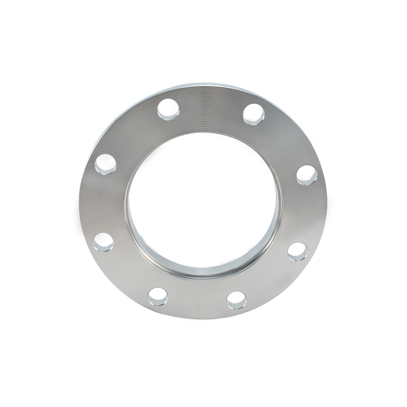 ASTM A105 Carbon Steel Flanges for High-Temperature PipingReview forged A105 flanges for ambient and high-temperature pressure systems, with custom sizes and sour-service requirements addressed at ordering.View Product →
One more material decision sits on top of the grade: sour service. Where the stream carries wet hydrogen sulphide, the flange and the plate holder have to meet NACE MR0175 or ISO 15156, which imposes hardness limits on the parent metal and the weld. That requirement belongs on the purchase order, not in a conversation after the heat treatment is finished.
Five Tolerances That Decide Whether the Meter Reads Correctly
Tap position, tap orientation, tap bore condition, face finish and bore concentricity are the five dimensions that separate a working orifice flange from an expensive blind flange with holes in it. All five are machined features, all five are cheap to hold at the machine, and all five are expensive to correct once the pair is welded into the line.
- Tap position. For flange taps, ISO 5167-2 places the centerline of each pressure tap 25.4 mm from the corresponding face of the orifice plate. A tap drilled 3 mm out changes the effective tap spacing and biases the discharge coefficient, which produces a systematic error rather than random scatter.
- Tap orientation. Both taps have to end up in a usable plane: horizontal for liquid and steam service so impulse lines drain and vent correctly, and vertical or angled for dry gas. Because orientation is fixed by the angular position of the tap relative to the bolt holes, that angle belongs on the drawing.
- Tap bore condition. Taps are normally 1/2 in. NPT in Class 300 and 3/4 in. NPT in Class 600 and above. Drilling or tapping after the facing operation leaves burrs inside the bore, and a burr changes the effective tap diameter and adds a local pressure loss that the transmitter reads as flow.
- Face finish. Raised face orifice flanges are finished between 125 and 250 microinch Ra, the same band as any B16.5 joint. A scored or over polished face will leak long before the taps become the main problem, and it is also the defect inspectors notice first.
- Bore concentricity and plate clearance. The orifice plate locates on the flange bore, so an off-centre bore pushes the plate off the pipe axis and adds an eccentricity term to the flow equation that no amount of transmitter calibration will remove.
25.4 mm
The distance from each orifice plate face to the centerline of a flange tap under ISO 5167-2. It is the most frequently missed dimension on a receiving inspection report, because it cannot be measured until the plate and gaskets are installed.
Jack Screws, Gaskets and the Installation Habits That Break Orifice Flanges
Jack screws exist for one purpose: to push the two flanges apart by the thickness of the gasket and no further, so the orifice plate can be removed and replaced. Using them to spread a misaligned pipe or to pull a spool into position bends flanges and strips threads.
The damage is almost always a sequencing problem. Jack screws are turned a fraction of a turn at a time, in rotation, with the line depressurised and the flange bolts loosened evenly. Forcing one screw while the others are still tight tilts the flange, loads the gasket unevenly and leaves a joint that weeps as soon as the line is pressurised.
The joint that leaks after a plate change is almost never the gasket's fault. It is the old gasket that went back in, the jack screws that were torqued before the bolts, or a plate handle left pointing upstream.
Gasket selection follows the same logic as flange material selection. Spiral wound gaskets with flexible graphite filler cover the high temperature and high pressure end of the range, while PTFE and PTFE faced gaskets cover low temperature and highly corrosive service where graphite is not acceptable. Whatever the material, the gasket is single use, and the jack screw threads and holes have to be clean and free of swarf before the pair goes back together.
Sourcing Orifice Flanges: Standard B16.36 Pair or Custom Machining
Buy a standard B16.36 pair when the line is between NPS 1/2 and NPS 24 in Class 300 through 2500, and switch to a drawing based forging when the line is larger, the facing is unusual, or the taps have to match an existing meter run exactly.
Standard B16.36 pair
- Tap size and position fixed by the standard tables
- Body dimensions identical to the B16.5 flange it replaces
- Shortest lead time and lowest unit cost
- Limited to NPS 1/2 through 24 and Classes 300 to 2500
Custom tapped pair to drawing
- Tap size, tap angle and jack screw layout set by the client drawing
- Covers line sizes above NPS 24 and non-standard facings
- Can combine an orifice tap with a ring joint or special facing
- Needs a tap dimensional report, because the standard table no longer applies
Whether a specific service is covered is worth checking against the manufacturer's application overview before the drawing is frozen, because the tap geometry and the facing specification usually change together on non-standard work.
Whatever the route, six items belong on the enquiry and on the final purchase order:
- Standard, edition and any project specification that overrides it.
- Size, class, facing type and the specified face finish in microinch Ra.
- Material grade, heat treatment condition, and any sour service requirement such as NACE MR0175 or ISO 15156.
- Tap size, tap position measured from the flange face, and the angular position of each tap relative to the bolt holes.
- Jack screw size, quantity, and whether the screws are supplied fitted.
- Marking, material certification, and whether a dimensional report on the taps is required at delivery.
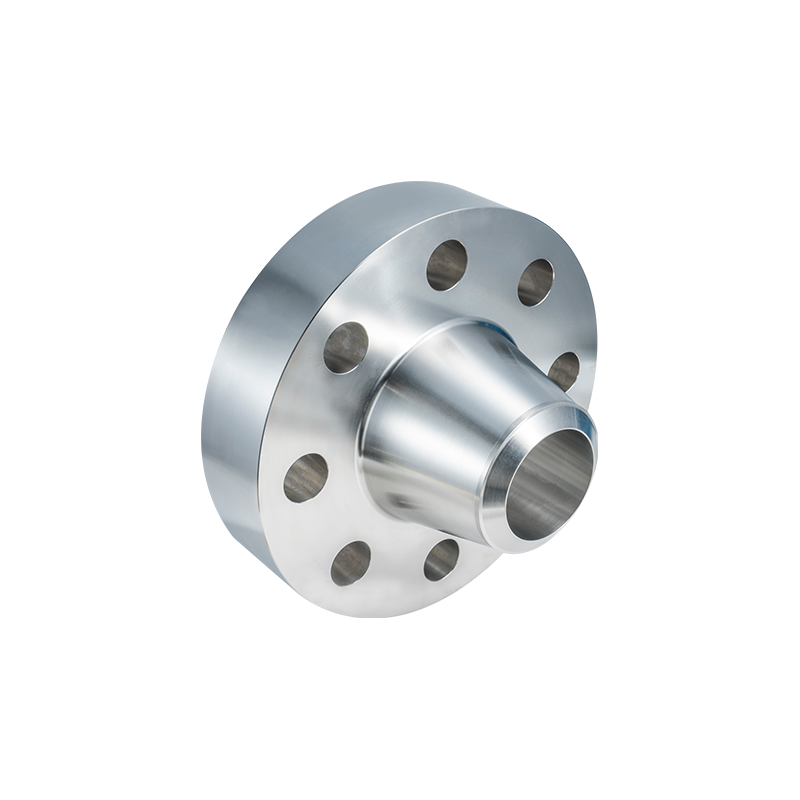 High-Pressure Weld Neck Flanges for Critical PipingExamine custom WN flanges with long tapered hub, up to 2500lb and 4m, for stressed high-pressure piping and equipment.View Product →
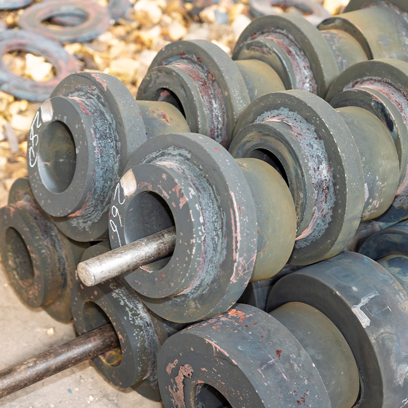 Custom Non-Standard Forged Flanges and Machined RingsBrowse custom flanges, rings, and machined parts made to drawings, with sizes to 4m, pressures to 2500lb, and varied materials.View Product →
For buyers who need standard and drawing based supply from one source, Jiangyin Zhonghai Precision Machinery Co., Ltd. (Jiangyin, Jiangsu, China) is an ISO 9001 certified flange and forging manufacturer working to GB, ASME, ASTM, JIS, EN and DIN standards, with PED, TUV and TS approvals. The company states that its in-house line covers forging, heating, CNC turning, drilling and inspection, and that its size range runs from 1/2 in. to 60 in., with single pieces up to 10 tonnes and maximum overall dimensions of 4 metres. That combination of a standard catalogue and a non-standard forging line is what makes a tapped or oversized orifice flange pair practical to quote rather than a special project.
Frequently Asked Questions About Orifice Flanges
What is the difference between an orifice flange and a weld neck flange?
An orifice flange is a weld neck or slip-on flange body with two added features: a radial pressure tap machined to a controlled distance from the face, and jack screws for separating the pair during plate changes. Body dimensions, bolting and facings follow ASME B16.5, while the tap and jack screw geometry is defined by ASME B16.36. A standard weld neck flange has neither feature and cannot be substituted without machining.
What size are the pressure taps on an ASME B16.36 orifice flange?
Class 300 flanges normally use 1/2 in. NPT taps, while Class 600 and above normally use 3/4 in. NPT. The taps are drilled radially through the flange wall and must be deburred, because the tap bore is part of the measurement path. Confirm the tap size and thread form on the drawing, since some projects standardise on one tap size across all classes for spares commonality.
Can orifice flanges be supplied with ring joint facings?
Yes, in the higher classes where the joint has to hold at high pressure or high temperature. A ring joint facing changes the groove dimensions, the gasket and the required ring number, all of which follow ASME B16.20 for the gasket. The taps and jack screws are unaffected, but the facing must be specified on the drawing rather than assumed from the class alone.
How do I specify an orifice flange above NPS 24?
Above the B16.36 range the pair is made to a drawing based specification, usually from a forged blank or a rolled ring, with tap position, tap angle, jack screw layout and facing all defined by the client. Forged flange manufacturers that run their own press and heat treatment line can cover these sizes, and the company above publishes a working range up to 60 in. with individual pieces to 10 tonnes, which is the practical boundary for large line metering spools.
 Previous