English
 中文简体
中文简体 Deutsch





Content
- 1 01What Are Flange Standards?
- 2 02When Non-Standard Flanges Are Required
- 3 03Standard vs. Non-Standard Flanges
- 4 04Why a Clear Drawing Is the Foundation
- 5 05How to Design a Non-Standard Flange
- 6 06Technical Specifications and Key Performance Factors
- 7 07Customizing a Large Non-Standard Flange
- 8 08Application Scenarios
- 9 095 Common Flange Problems and How to Troubleshoot Them
- 10 10Selection Considerations for a Manufacturing Partner
- 11 11Common Mistakes and Overlooked Considerations
- 12 12Conclusion
- 13 Frequently Asked Questions
- 13.1 What are the flange standards?
- 13.2 What are common flange problems?
- 13.3 How do you design a non-standard flange?
- 13.4 Why is a clear drawing the foundation of a custom flange?
- 13.5 When is a non-standard flange necessary instead of a standard one?
- 13.6 How do you customize a large non-standard flange?
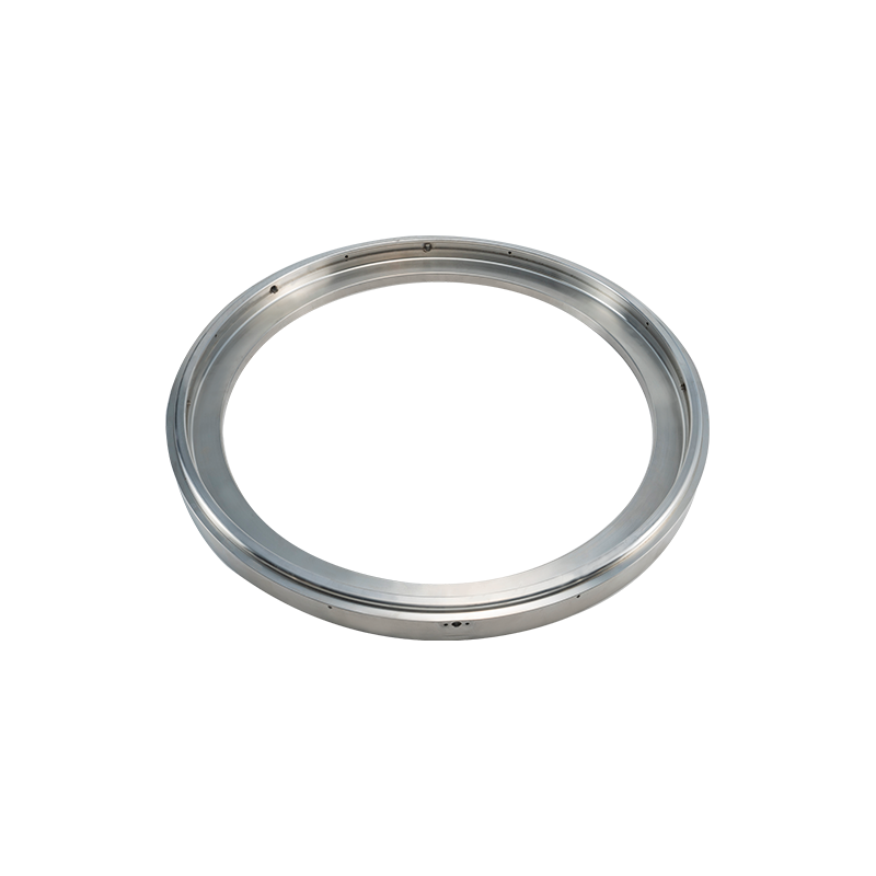
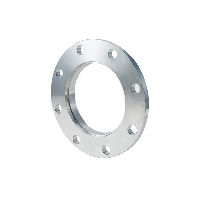
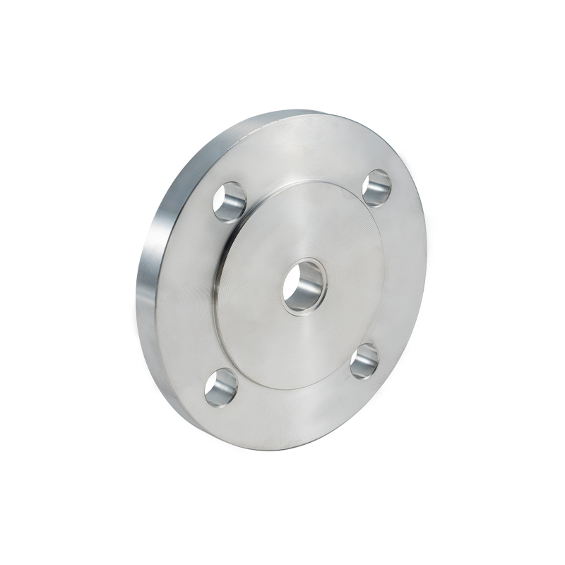
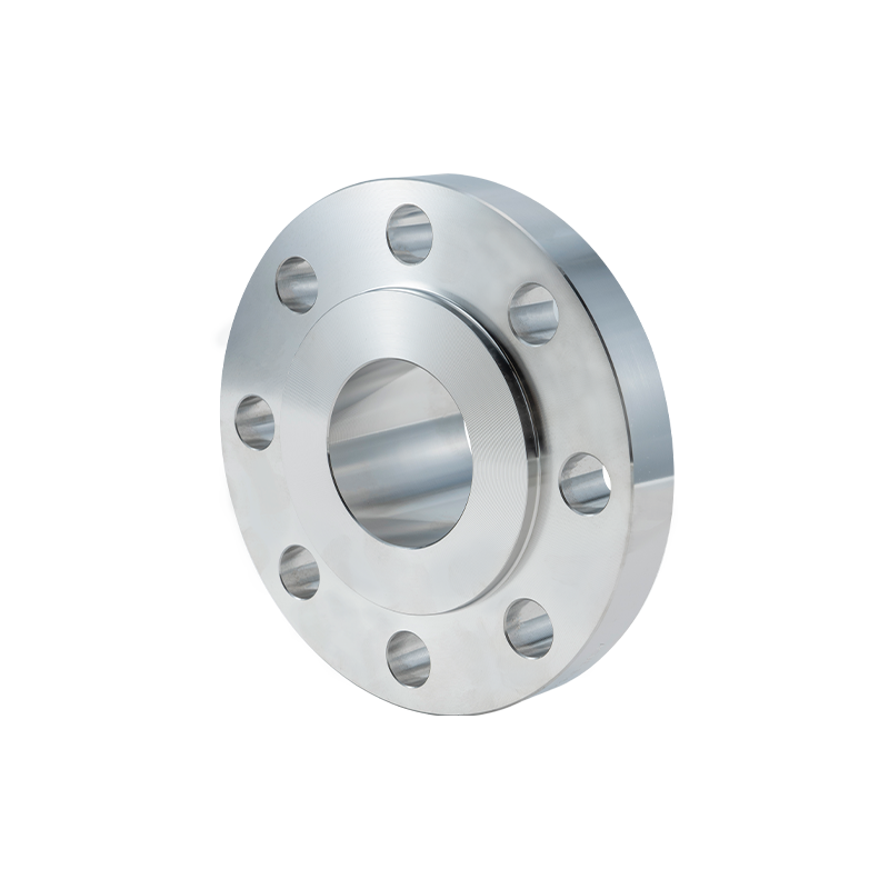
Non-standard flanges are flange components manufactured to dimensions, pressure ratings, or material specifications that fall outside the scope of published standards such as ASME B16.5, EN 1092-1, or GOST 12820. They are produced from project-specific drawings rather than catalog tables, allowing a flange to be matched precisely to conditions that a standard part cannot meet.
Drawing-Based Produced from project drawings, not catalog tables
Custom Ratings Pressure and temperature values outside standard classes
Custom Geometry Bore, bolt circle, and facing adjusted to fit
Material Flexibility Forged in the alloy the application calls for
01What Are Flange Standards?
Flange standards define fixed combinations of bore size, pressure class, bolt hole pattern, and facing type so that flanges from different manufacturers can be interchanged reliably. Widely referenced standards include ASME B16.5 and B16.47 for the North American market, EN 1092-1 across much of Europe, JIS B2220 in Japan, and GOST 12820 in markets that follow Russian and CIS specifications. These frameworks work well for the overwhelming majority of piping systems, where dimensions and operating conditions fall within a predictable range.
A standard is, by design, a generalization. It is built to cover common combinations of pipe size, pressure, and temperature efficiently. When a project's conditions sit outside those combinations, the standard itself no longer describes a part that fits the application, which is where a drawing-based approach becomes necessary.
02When Non-Standard Flanges Are Required
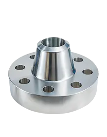
Non-standard flanges are generally used only in cases where pressure, temperature, or size requirements exceed the capabilities of standard flanges. This includes pipe diameters larger than what standard tables cover, pressure classes that fall between two published ratings, operating temperatures near the edge of a material's rated range, or connection points that must mate with existing legacy equipment built to an obsolete or regional specification. In each of these situations, a non-standard flange is engineered to the exact working conditions rather than rounded up or down to the nearest standard size.
03Standard vs. Non-Standard Flanges
| Aspect | Standard Flange | Non-Standard Flange |
| Design basis | Published standard table | Project-specific drawing |
| Size availability | Fixed set of sizes | Any size within manufacturing capability |
| Pressure and temperature range | Defined pressure classes | Matched to actual working conditions |
| Lead time | Typically shorter, often stock-based | Longer, dependent on drawing approval and tooling |
| Documentation | Reference to standard number | Full technical drawing with tolerances |
| Typical use case | Conventional piping systems | Legacy equipment, oversized lines, unusual ratings |
04Why a Clear Drawing Is the Foundation
Every dimension, tolerance, and material property on a non-standard flange traces back to a single source: the drawing. Without a complete and unambiguous drawing, no two production runs can be guaranteed to match.
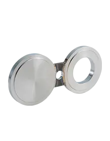
Because a non-standard flange has no published reference table to fall back on, the drawing carries the full weight of defining the part. A drawing intended for production should specify outside diameter, bore diameter, bolt circle diameter, number and size of bolt holes, thickness, facing type and finish, and material grade, along with applicable tolerances for each dimension. Incomplete drawings are one of the most frequent sources of delay in custom flange projects, since missing tolerances or ambiguous facing callouts require clarification before machining or forging can proceed.
05How to Design a Non-Standard Flange
Define Working Conditions
Establish the actual operating pressure, temperature, and media the flange will handle, rather than relying on the nearest standard class.
Select the Base Material
Choose a forging or casting material grade suited to the working conditions, considering corrosion resistance, mechanical strength, and compatibility with the connecting pipe.
Set Geometry and Facing
Define bore size, bolt circle, number of bolt holes, and facing type (flat face, raised face, or ring joint) based on how the flange will mate with adjoining equipment.
Prepare a Complete Drawing
Document every dimension and tolerance so the part can be reproduced consistently across production runs.
Validate Before Full Production
Review the drawing against the intended installation, and where practical, confirm fit with a first-article inspection before committing to a full production batch.
06Technical Specifications and Key Performance Factors
| Specification | Typical Range or Consideration |
| Material | Carbon steel, stainless steel, alloy steel, or duplex grades depending on media and pressure |
| Pressure rating | Defined by working pressure rather than a fixed class |
| Temperature range | Matched to process conditions and material rating |
| Facing type | Flat face, raised face, or ring type joint depending on sealing requirement |
| Bolt circle and drilling | Custom hole count and spacing to match mating equipment |
| Dimensional tolerance | Set by the approved drawing rather than a standard tolerance table |
07Customizing a Large Non-Standard Flange
Large-diameter flanges introduce additional considerations beyond scaling up a smaller design. Forging equipment must have sufficient capacity to produce a blank of the required diameter and thickness without compromising grain structure. Machining large flat faces evenly requires equipment capable of holding flatness tolerances across a wide surface, since even small deviations become more significant at scale. Heat treatment cycles also take longer for large forgings, and uneven cooling can introduce internal stress if not carefully controlled. For projects involving oversized flanges, confirming a manufacturer's forging press capacity and machining bed size early in the process helps avoid mismatches between drawing intent and production capability.
08Application Scenarios
- Petrochemical processing: Pressure vessels and piping runs operating at combinations of pressure and temperature outside standard classes.
- Offshore and marine platforms: Connections that must interface with existing structural steel or legacy piping built to older specifications.
- Power generation: Boiler and turbine piping where thermal cycling demands precise tolerance control.
- Oversized pipeline projects: Large-diameter transmission lines that exceed standard flange size tables.
- Equipment retrofits: Replacement flanges matched to decades-old equipment no longer covered by current standards.
095 Common Flange Problems and How to Troubleshoot Them
1
Selecting the Wrong Size
Confirm bore, bolt circle, and outside diameter against the mating equipment drawing before ordering, rather than relying on nominal pipe size alone.
2
Wear and Tear
Inspect sealing faces periodically for surface degradation, particularly in systems with abrasive or corrosive media.
3
Stripped and Worn Bolts
Use the correct bolt grade and torque specification for the flange rating, and replace bolts showing thread wear rather than reusing them.
4
Thermal Shocks
Allow gradual temperature changes where possible, since rapid thermal cycling can loosen bolted connections or distort sealing faces over time.
5
Excessive Leaks
Check gasket compatibility with the process media and confirm even bolt torque distribution, since uneven loading is a frequent cause of localized leak paths.
10Selection Considerations for a Manufacturing Partner
Choosing a source for non-standard flanges involves evaluating more than price. Relevant factors include available forging capacity for the required size range, in-house machining tolerance capability, material traceability documentation, and experience reviewing and clarifying custom drawings before production begins.
- Forging and machining capacity: Confirm equipment can accommodate the required diameter, thickness, and tolerance without subcontracting critical steps.
- Material traceability: Request mill certificates and heat numbers that trace back to the original material batch.
- Drawing review process: A manufacturer that reviews drawings for ambiguity before production reduces the risk of dimensional errors.
- Testing and inspection options: Availability of dimensional inspection, hydrostatic testing, or material testing appropriate to the application.
11Common Mistakes and Overlooked Considerations
- Omitting tolerance callouts: A dimension without a stated tolerance leaves interpretation open to the machinist, which can result in parts that do not fit.
- Skipping material certification requests: Without documented traceability, verifying that the correct material grade was used becomes difficult after the fact.
- Overlooking facing and gasket compatibility: A facing type mismatched to the intended gasket is a common and avoidable cause of sealing issues.
- Underestimating lead time for large forgings: Oversized or unusual configurations often require longer production timelines than standard parts.
12Conclusion
Non-standard flanges exist to solve a specific problem: matching a flange to conditions that published standards do not cover. Their value depends entirely on the quality of the drawing behind them, the suitability of the material selected, and the manufacturing capability applied to produce them. Understanding when a standard flange is no longer sufficient, and what information a manufacturer needs to produce an accurate non-standard flange, helps ensure the finished part performs as intended from the first installation.
Frequently Asked Questions
What are the flange standards?
Common flange standards include ASME B16.5 and B16.47, EN 1092-1, JIS B2220, and GOST 12820, each defining fixed size, pressure class, and drilling combinations for a given market or industry.
What are common flange problems?
Frequent issues include selecting the wrong size, wear and tear on sealing faces, stripped or worn bolts, damage from thermal shocks, and leaks caused by gasket or torque issues.
How do you design a non-standard flange?
Design begins with defining actual working pressure and temperature, selecting a suitable material, setting geometry and facing type, and preparing a complete drawing with full tolerances before production.
Why is a clear drawing the foundation of a custom flange?
Because no published standard applies, the drawing is the only reference defining every dimension and tolerance, so any ambiguity in it directly affects the accuracy of the finished part.
When is a non-standard flange necessary instead of a standard one?
When pressure, temperature, or size requirements fall outside what standard flange tables cover, including oversized pipe diameters or connections to legacy equipment.
How do you customize a large non-standard flange?
Large custom flanges require confirming forging press capacity, machining bed size, and controlled heat treatment to maintain flatness and material integrity at scale.
 Previous